Big Turbo Problem
Now the last thing
I want you to think is that it was lack of planning that
caused this problem - bigger is not
always better (even for sports car drivers!) and it wasn't sheer
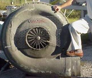
greed for "more blow" here... or I could have just sought out
the "mother of all turbos" as in the photo here! (now that IS a
big turbo!!!)
I actually spent many hours studying these parameters of the
latest and greatest ball bearing turbos, to find the perfect
match for the engine:
matching graphs (pressure Vs air flow)
- it's not just all about maximum boost, you need the turbo to
pump as much air as the engine requires for a given power output
too), trim (compressor/turbine
rotor diameter ratio) - affects turbo size, spool
time and boost/flow), A/R ratios
(housing geometry ratio for both turbine ane compressor)
- again affects turbo size, spool time and boost/flow) etc.
I also wanted the turbos to bolt straight in place
of the old T25s if at all possible, so size was always a factor
and also using a turbo with the same T25 exhaust mounting flange -
the RIGHT turbos for the engine tune level was the ultimate
concern though - I wasn't going to all the trouble of
modifying the engine to extent that I have, only to limit the
final output by the selection of turbos
The common use of "reflowed" T25s with 360 degree
bearings, or "hybrid" T28s, are really comprimises to try and
achieve more flow in the existing T25 form factor - they are never
going to supply the boost and flow plus rapid spool up that I want
So Pick the best turbos -
if they fit, all well and good - if they don't, they will be
fitted somehow, whatever it takes!
My fnal choice was the GT28RS - also known as the "Disco Potato"!
Actually this name even appears on the Garrett
product catalogue and was coined by them from the shape of the
turbo map
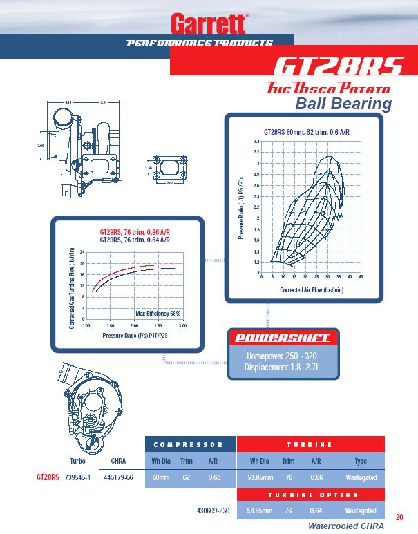
The Garrett GT range all have a dual ball bearing
assembly instead of floating oil bearings of older designs like
the T25 - they spool much faster and also have greatly improved
turbine/compressor aerodynamic properties
It's always difficult to get a "free lunch" though
and the more common .86 A/R turbine vesrion gives very high power
but would be some what laggy on capacities under 2.0 litres (the
3.5 litre V8 equates to 1.75 litres per bank)
More research (and cutting though sales talk!)
revealed that there is a lesser known
.64 A/R GT28RS - with this more efficient aero and ball
bearings, this should provide spool as quick as the
old T25s but hugely increased power capability
Before buying, I also emailed a few suppliers for
their views - Click here to view the
trail
On first inspection the GT28RS look impressive and definitely "man
enough for the job"
The Exhaust turbine housing, although having a very
different outlet (5 bolt exit, for a V-band adapter with larger
bore exhaust) didn't seem much larger than that of the T25s
The inlet air compressor is
much larger though - even the inlet is 3 inch, a full inch
larger than the T25s, as the photo on the right shows (GT28RS
on left T25 on right)
The alignment of the CHRA (Centre Housing Rotating
Assembly) wasn't correct for the oil banjos and coolant lines to
line up, but this can be loosened and moved without affecting the
balancing
The exhaust flange was the right pattern, but the
drilled holes were smaller than that of the T25 - this isn't too
hard to correct, so I started trying the turbos in position
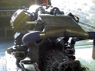
and, as the photos below show, they looked magnificent.....
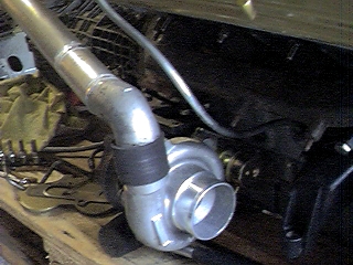
Take a closer look at the photos though - when I offered the
lovely new GT28RSs up to the exhaust manifolds - although I
couldn't put them on the studs because of the hole sizes, it was
clear that even if I could, the
compressor housing comes very close to the block on the near
side and the large 5 bolt exhaust exit would foul the bell
housing on the off side... OH DEAR!
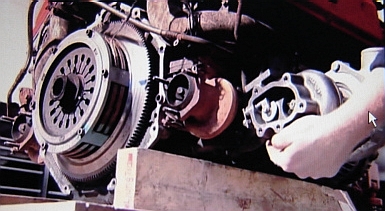
Here's a photo borrowed from a recording of 5th Gear (the full
video is on the 5th Gear section)
My contact, GW, is holding up a GT28RS next to the T25 in situ -
it's obvious how close the T25 small exhuast exit comes to the
bell housing and that the GT28RS won't fit in the same
position!
Sitting there with the engine and turbos, a thought occurred to me
(probably at the same time as realising that the foolproof, but
expensive option, was repositioning the turbos completely and
fabricating completely new, one off, manifolds) that more
clearance could be afforded by spacing the exhaust manifolds out
at their natural 45 degree angle (moving the turbos downwards and
outwards)
It was time to share these findings with the PM71 project team
- Click here to read
the email trail
I made up the annotated pictures below to explain the
situation and how a manifold spacer could possibly be used
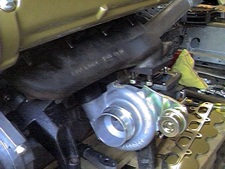
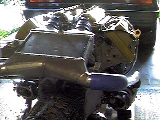
In a positive vane, I also took these photos with the turbos in
the positions they would adopt with manifold spacers - they just
might just be propped up on mallets, but they do give a good
impression of how it would look
They certainly look a significant upgrade to T25s and clearly
what's needed to match the rest of the modofications to the
induction... I know I'm doing the right thing insisting on
getting them fitted!
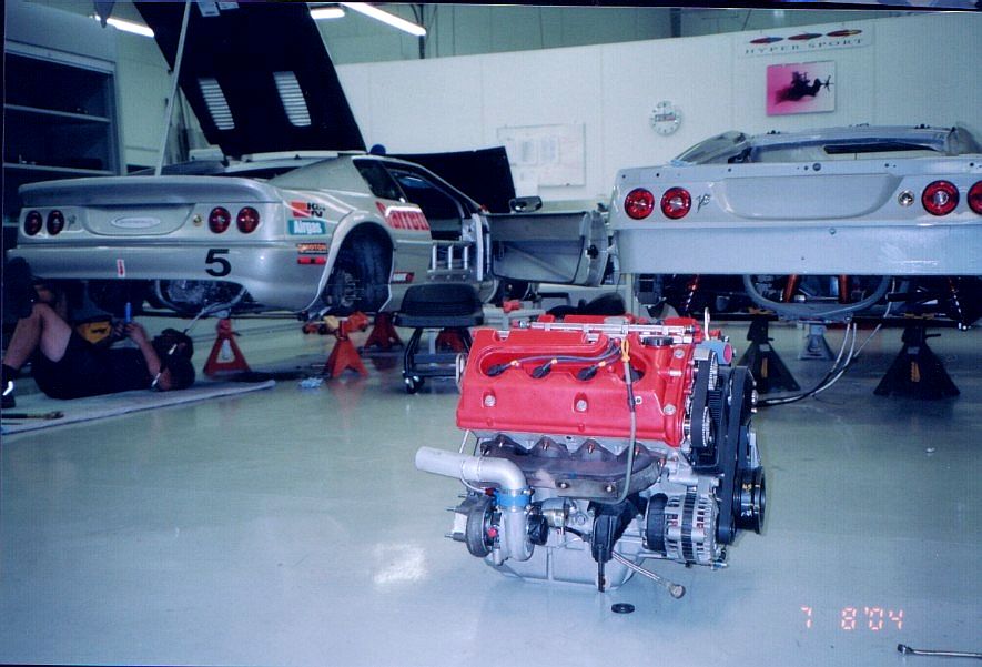
Now, whilst I was surfing the Net, I happned across a post about
an Esprit V8 being prepared by Garrett
themselves for a racing series in the USA
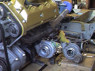
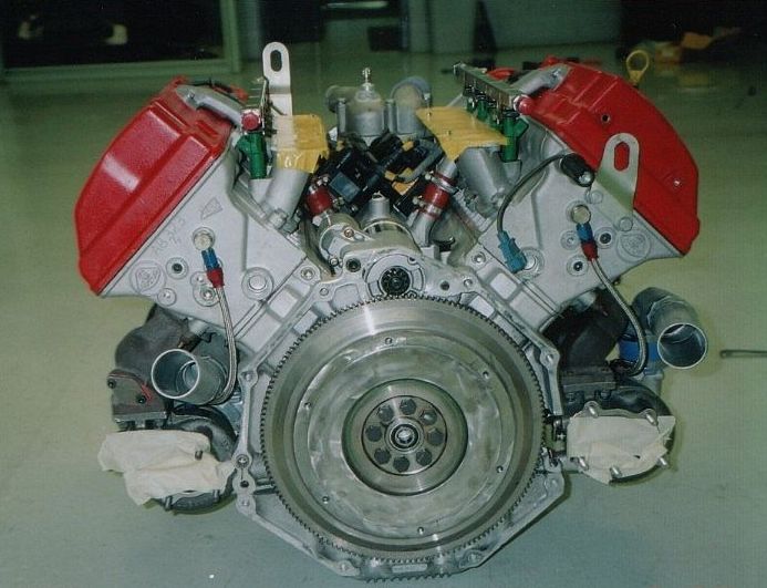
It was clear from the photos that, as you might expect of
Garrett, they were changing the turbo installation - the shot on
the right shows the engine in the workshop, with modified plumbing
for connection to their chargecooler (photo
in "Engine" section of "Design" section)
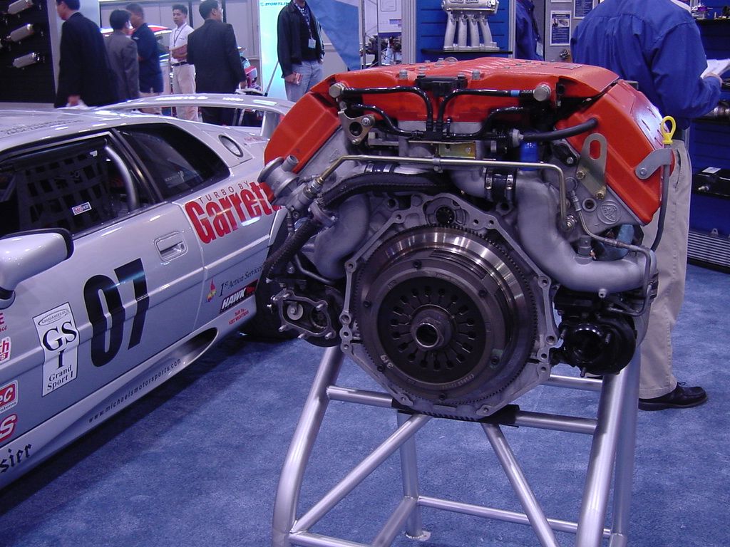
This shot shows the car with an engine on stand at an exhibition
- but click for the enlargement and look closely at both turbos...
the one on the right has the old 3 bolt exhaust exit (probablt
a T25), but the one on the left has a new 5 bolt exit!
I emailed the message board, got the Garrett and race teams
contact info and emailed them to find out what was going on - Click here to read the email trail
So the answer was that they were using GT25R turbos (that
have the 5 bolt exit but are not as large as the GT28RS) - the
photo on the right shows how the team have cut a slot in the bell
housing to fit the right hand GT25R.
The dimensions of my GT28RSs look like they make
even drastic measures like this, less than what is needed - they
need to be spaced away from the engine/transmission
However, this means that they encroach on the
chassis tube that runs very close to the outer side of the turbo
The annotated picture from beneath the car illustrates the
problem here - without the engine being fitted to the chassis, it
is very difficult to gauge how much room I have to play with here
I may, of course, have to fit the engine in order to find the
optimum position for the turbos and the exhaust manifold
arrangement
This isn't a step I planned on doing though - I'd rather
find a way to keep to my plan of developing the complete
engine/induction, map the ECU at the dyno/engine cell and then
start the assembly
You'll notice from the underside view that the exhasts have to
take a fairly sharp vertical "dog-leg" over the drive shafts too.
So moving the turbos rearwards would exacerbate this problem.
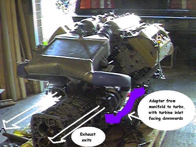
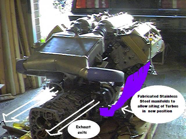
If I do completely reposition, I'll probably use the
position shown on the right here - this will allow straight
exhaust exits to the rear of the car, won't present oil drain
issues and provides an even shorter inlet to the chargecooler
The diagram shows a cheaper alternative of using an adapter pipe
from the standard manifolds - but this position could also be
used with fabricated stainless steel manifolds
Either way I'm concerned about the length of the pipework to
the turbines - exhaust manifold design is quite complex
because of the way the pressure pulses from each cylinder combine
- this is important on normally aspirated engines to provide an
"extractor" effect but it is key on turbocharged engines to ensure
spooling of the turbine
The odd and even cylinders are combined in the primaries and the
two bores are kept seperate right up to the turbo inlet on the
standard manifolds) - the thing to avoid is what's called pulse
reversion - where the exhaust gas travles in the wrong
direction! It is possible to merge the primaries at a
"collector" point and then run a secondary pipe to the turbo, but
distances/dimensions are important....
Well that's the
Big Turbo Problem defined - what the solution is, I'm not
absolutely sure yet!
Oct 2011:
I am definitely having stainless steel manifolds fabricated
now - after a chat over lunch during a track day at Brands Hatch,
the ideal company has come to light...
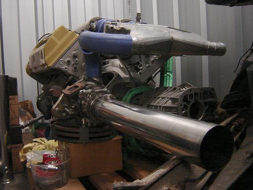
Here's one the GT28RS turbos propped up on the clutch (which will
probably also need an upgrade for high power/torque) showing the
approximate position where the new manifold should meet it